1. Introduction
The accelerated 5G cellular network rollout in the Asia-Pacific region has speeded up the installation and use of 5G rejection bandpass filters (BPF) for satellite television receive-only (TVRO) antenna systems. In Hong Kong alone, more than one thousand C-band TVRO antenna systems or satellite master antenna television (SMATV) systems have been upgraded with 5G rejection BPF, where a great portion of the antennas were upgraded using AsiaSat’s 5G filters.
AsiaSat 5G rejection BPF has been put on the market since 2019 and has been well received in the satellite TV community. With its compact profile, light weight and excellent 5G rejection performance, the BPF has become an essential component for a C-band satellite reception site.
This paper has been updated to include some of our latest experience in troubleshooting real-world use cases involving BPF installation.
- Troubleshooting Case 1 (2020): A 5G interference issue occurred at a C-band satellite TV receiving terminal. This was caused by a loose BPF-LNB connection and poorly designed LNB, specifically a leaky body and a non-metallic interface.
- Troubleshooting Case 2 (2025): 5G interference affected a C-band mobile terminal used for data service. This problem stemmed from a poor BPF-LNB connection caused by the blind holes used on the LNB input interface.
Since the quality standard of the BPF installation could significantly impact the 5G rejection filter’s performance and hence the satellite-TV and data service’s user experience, we are sharing our experience in order to provide some diagnosis guidelines that may be helpful for BPF installation.
2. Real 5G Rejection BPF Installation Troubleshooting Case 1 (2020)
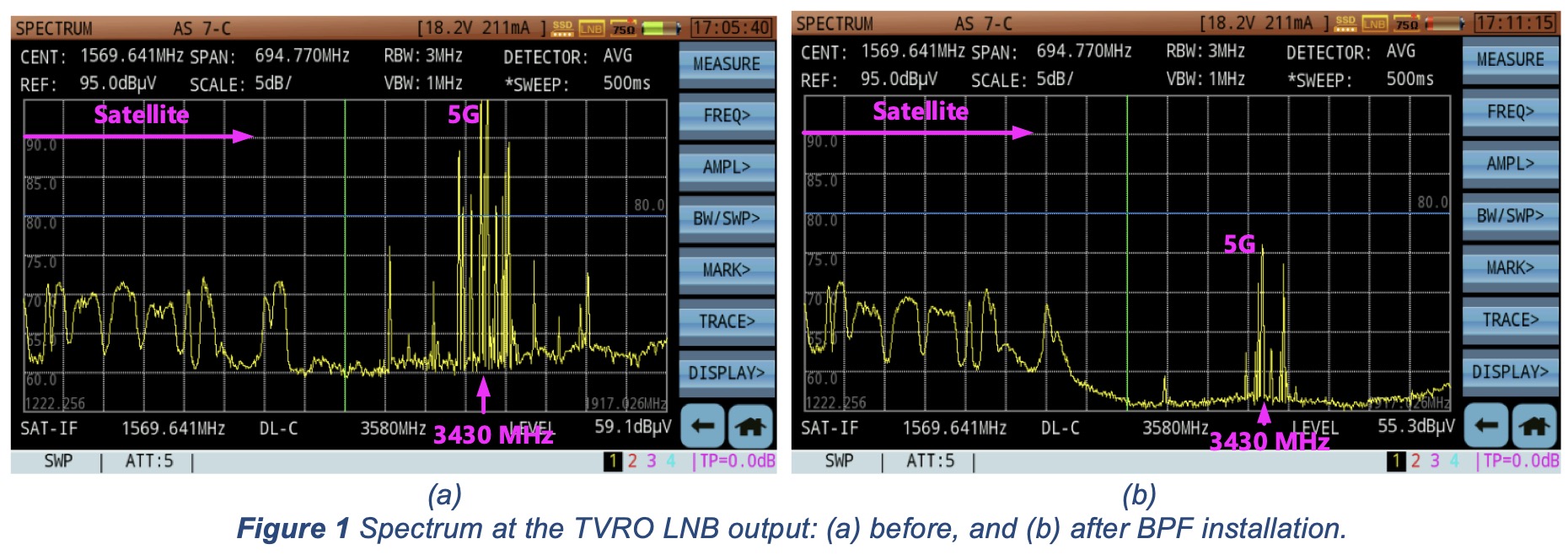
One of our customers has reported that a recently installed 5G BPF did not function as expected – interference still occurred intermittently and impaired the satellite TV reception. The spectrum plots before and after BPF installation are shown in Figure 1(a) and (b).
It can be seen from Figure 1(a) that there was intensive 5G interference at around 3430 MHz, with a bandwidth of about 60 MHz. After the BPF installation, interference was reduced by only 20 dB, as shown in Figure 1(b), performing at a far lower level than the > 60 dB rejection level that AsiaSat BPF-3700S filter was designed to provide. The 5G interference to the TVRO system remained strong and “robbed” the satellite carrier power from the low noise block-downconverter (LNB), putting up mosaics on the TV screen.
2.1 Symptoms and the Preliminary Diagnosis
We started by asking our customer to describe the operational environment as well as the connection status of the equipment, e.g. the antenna feed horn, the BPF and the LNB.
According to the customer, no 5G base station shared the same rooftop with the satellite dish – which could have been the case for many buildings in Hong Kong. We were also told that there were no 5G base stations in the pointing direction of the satellite dish. In other words, there was no known reason why the 5G interference power would exceed the design limit of the 5G rejection BPF.
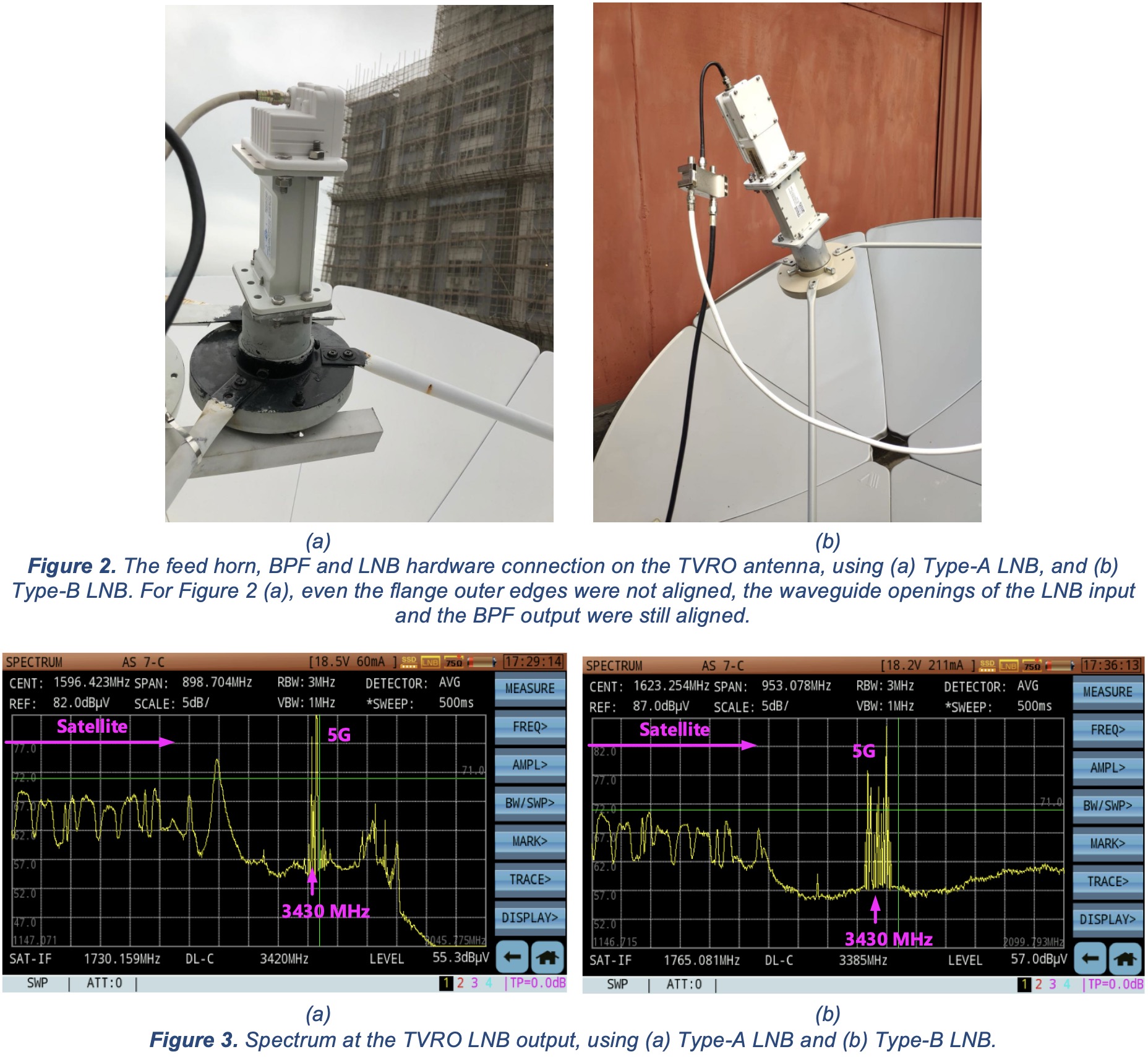
The customer sent us a close-up photo showing the connection on the TVRO equipment which is shown in Figure 2(a). It was a front-fed TVRO, and the Type-A LNB used by the customer was of a light-weight type secured by four screws and has a non-standard waveguide interface. The LNB was enclosed in a plastic shell and appeared not to be fully EMI-shielded.
For the sake of comparison and in an attempt to mitigate the problem, we asked the customer to repeat the spectrum measurement using a Type-B LNB with a full-metallic body and standard WR229 input interface. Figure 2(b) shows the hardware connection of the Type-B LNB, where 10 screws were used to secure the BPF. Unfortunately, there was no improvement in the level of 5G interference at the Type-B LNB’s output.
The spectrum plots comparison is shown in Figure 3.
2.2 On-site Diagnosis
Given the unsatisfactory result of the preliminary diagnosis and the failed attempt at mitigation, we decided to conduct a site visit in order to assess the TVRO site environment and to inspect the quality standard of the hardware installation.
Upon arriving at the customer’s site, we found the environment to be different from what we had expected. Unlike most rooftop-installed SMATV antennas, the TVRO antenna in question was located on the second floor balcony of an industrial building, overshadowed by skyscrapers of more than 30 stories high.
Figure 4(a) shows what appeared to be 5G base stations, and Figure 4 (b) shows that one of them was only 10 to 20 degrees from the pointing direction of the TVRO antenna.
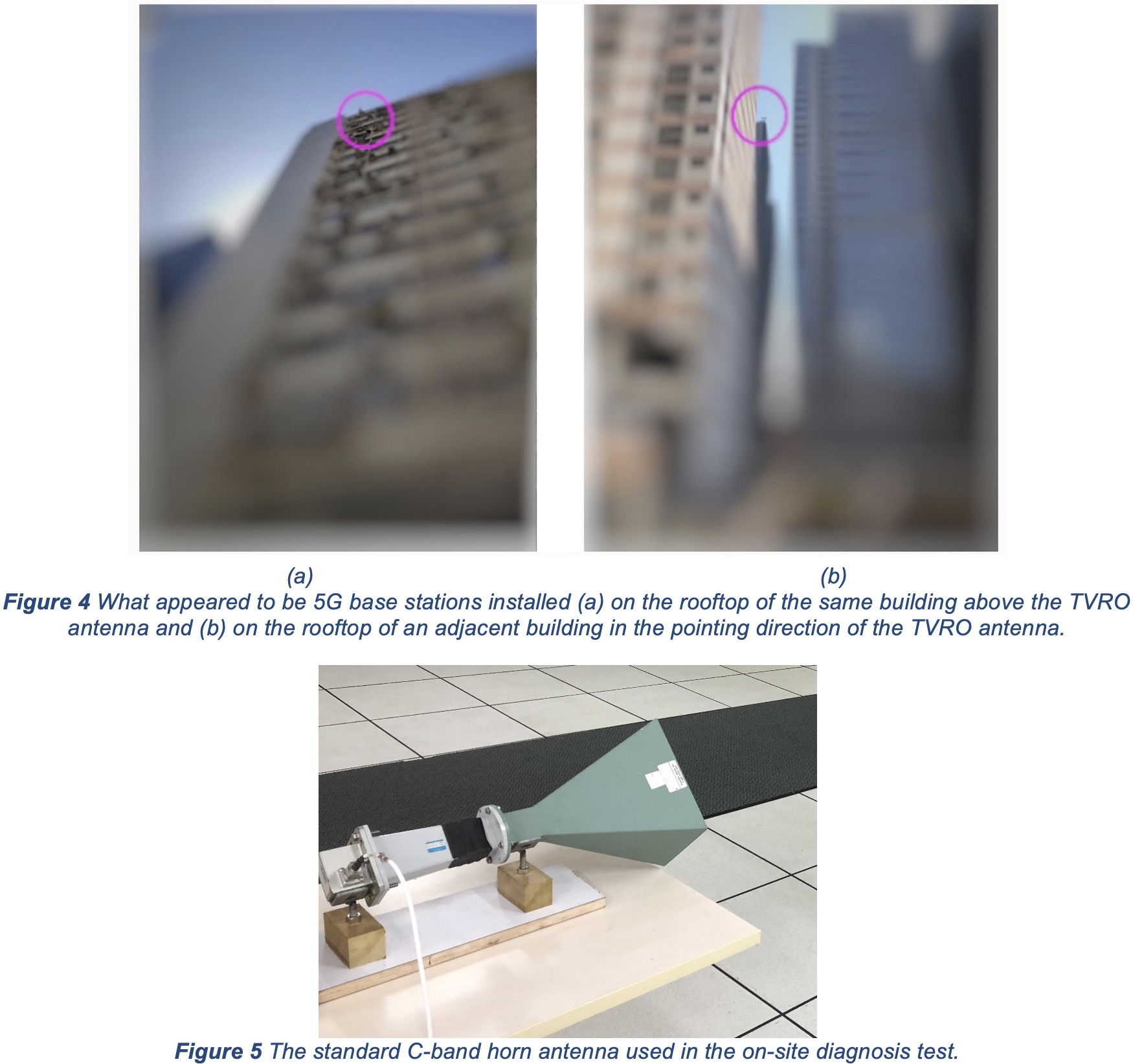
As a first step, we took an interference scan with a standard C-band horn antenna (see Figure 5). The horn was connected to a hand-held spectrum analyser, and we manually scanned the horn in all possible directions with max-hold spectrum plot. The scanning results confirmed that the 5G interference generally came from the rooftop of the adjacent building in the pointing direction of the satellite dish.
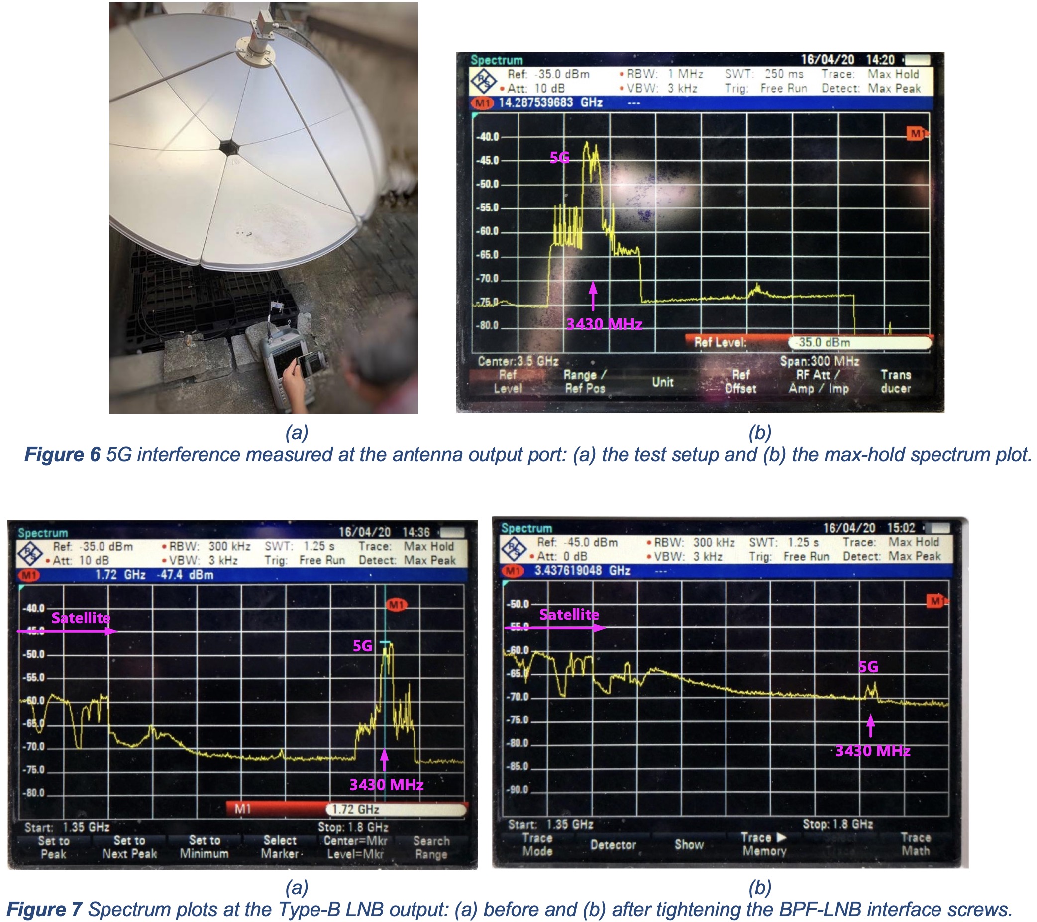
The second diagnosis step was to take 5G interference measurements directly from the antenna feed output as shown at Figure 6(a). The corresponding spectrum was max-held for more than 5 minutes and shown at Figure 6(b). It can be seen that the interference was in the typical 5G spectrum shape, where the inner 15 MHz wide plateau was made of 5G synchronising signal blocks (SSB) which were broadcast and used for establishing the links between the base station and the 5G end user equipment. The estimated 5G powerpicked by the satellite dish antenna was less than -33 dBm, which should have had no noticeable impact to the satellite carriers if the BPF had functioned normally.
The third diagnosis step was to inspect the BPF-LNB interface and tighten the screws. First, the BPF-LNB junction was removed from the feed horn. After careful inspection, no gaps or cracks at the BPF-LNB interface could be observed, and all the screws were fastened as shown in Figure 2(b). However, as we tried to tighten the screws, we found that 7 out of the 10 screws were not tightly fastened. The spring lock washers under the screw head were only slightly loaded. After tightening all the screws, we mounted the BPF-LNB junction back onto the feed, and the 5G interference was found to have gone immediately. It turned out that an imperceptible gap between the LNB and the BPF was the culprit! The spectrum plots comparison before and after the screw tightening is shown in Figure 7, and it can be seen that the tightened BPF-LNB interface has helped to reduce 5G interference by 20 to 25 dB.
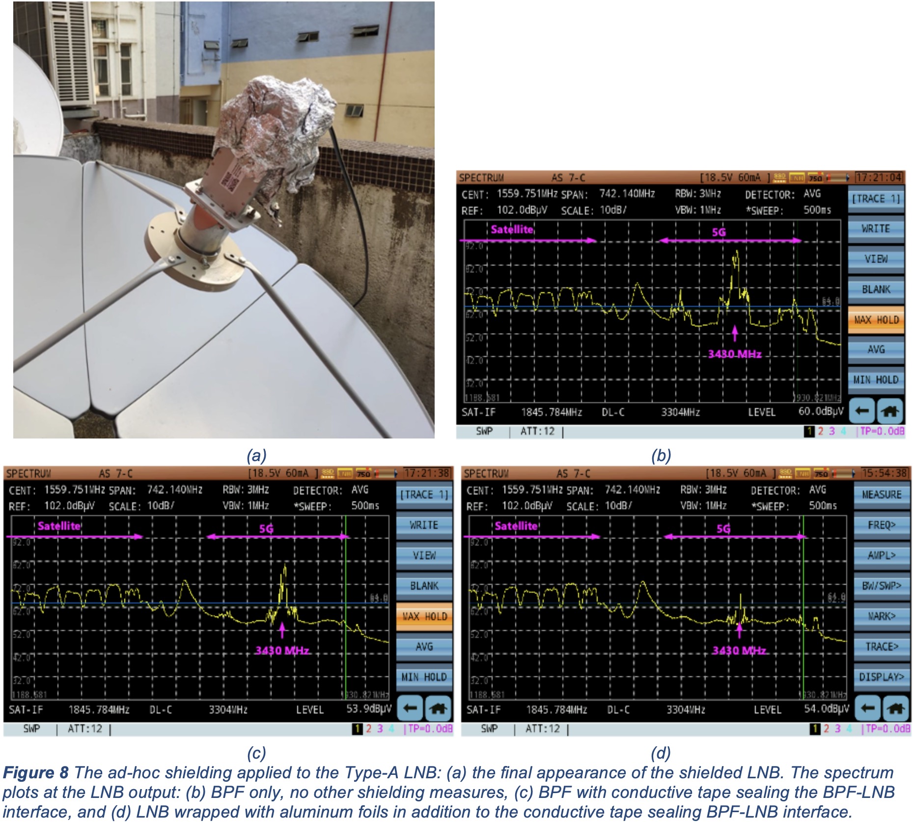
To further help the customer with the Type-A LNB as used in Figure 2(a), we tried several ad-hoc shielding methods and tested their effectiveness. First, all four screws at the BPF-LNB interface were tightened. The resultant spectrum plot at the LNB output is shown in Figure 8(b) where the 5G interference signal was still strong.
A layer of conductive tape was then applied to seal the BPF-LNB interface, and the corresponding spectrum plot is shown in Figure 8(c). The conductive tape improved the shielding effect by only a few dBs.
Finally, three layers of household aluminum foil were used to wrap the LNB, and the corresponding spectrum plot is shown in Figure 8(d). It can be seen the conductive tape combined with the aluminum foils provided a total shielding effect of 20 dB, and the 5G interference has been reduced to an acceptable level.
Figure 8(a) shows the final appearance of the LNB. Based on the tests, we suspected there was a leakage from the Type-A LNB (e.g. gaps or simply non-metallic body enclosure) in addition to the BPF-LNB connection interface. The tapes and aluminum foils may work as a temporary shielding, but their effects may be degraded by the elements over time.
3. Real 5G Rejection BPF Installation Troubleshooting Case 2 (2025)
A customer recently installed an AsiaSat BPF-3925 filter on their mobile terminal, replacing their existing BPF. Following the installation, they reported persistent communication interference issues despite the new BPF being in place. We troubleshot the case and found the culprit was still the untightened connection interface.
The installed AsiaSat BPF-3925 filter is designed for a passband of 3925 – 4200 MHz and a lower-frequency rejection band from 3000 up to 3900 MHz, offering greater than 60 dB rejection. This design is especially effective in regions where the 5G spectrum is allocated up to 3.9 GHz within the traditional satellite C-band. The filter has been extensively tested and is currently used by many other AsiaSat customers without issue.
However, in this case, the spectrum plot (Figure 9) provided by the customer revealed a significantly higher level of 5G carriers than the satellite carriers in the 3300 – 3600 MHz range. This range is far below the BPF-3925’s passband and should have been effectively rejected below the LNB noise level.
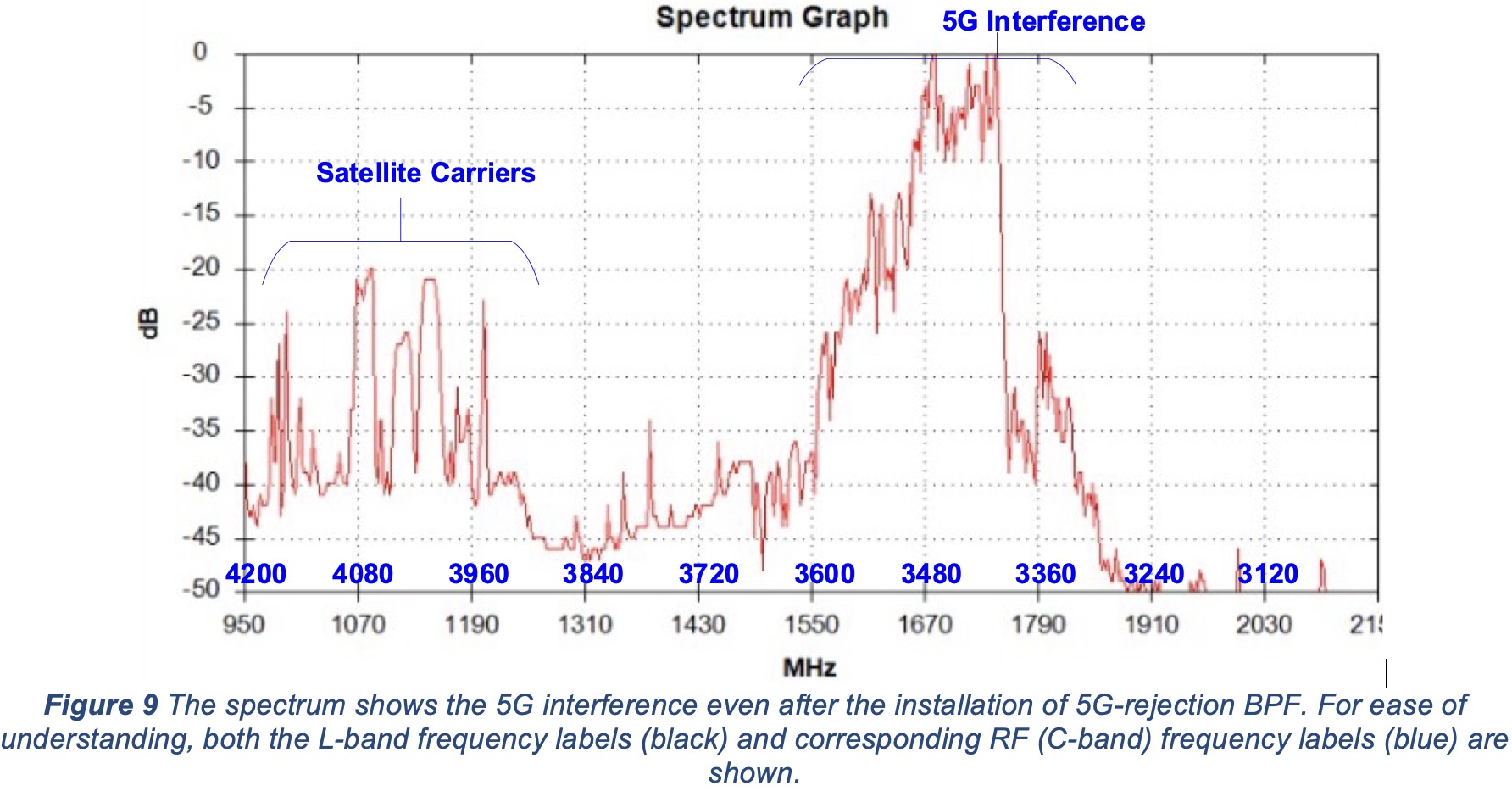
It can be seen that the satellite C-band carriers shown on Figure 9 are within the BPF-3925 passband frequency range (3925 – 4200 MHz), while the other satellite carriers and uplink noise mounts in the lower C-band spectrum (3700 – 3900 MHz) are not visible. This indicates that the filter functions as expected with respect to the satellite signals received by the antenna dish. The observed 5G interference might be picked up directly by the LNB rather than passing through the BPF.
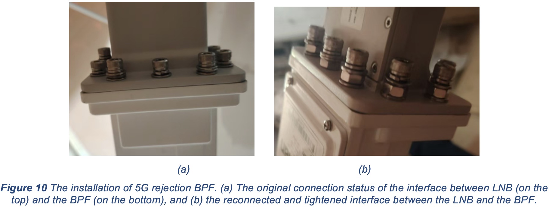
To verify this speculation, the customer was initially instructed to wrap the entire LNB and its interface to the BPF with aluminum foil. This action resulted in an interference reduction of nearly 20 dB. The customer also provided a close-up photo of the connection interface between the LNB and BPF as shown in Figure 10(a).
Typically, most LNB models feature through-holes on their flanges, allowing the LNB and BPF to be securely tightened together using screws and nuts on both sides of the interface. However, the LNB used in this specific installation case is different: It has only tapped blind holes on its flange, preventing the use of nuts on the opposite side. The screws used in Figure 10(a) are visibly longer than necessary. Even with addition of extra washers, the connection remained insufficiently tight, leaving imperceptible gaps that allowed 5G interference to enter.
For this reason, we recommended reinstalling the BPF using bolts that were pre-assembled with nuts as shown in Figure 10(b). This approach ensures the LNB-BPF assembly can be properly tightened before the bolts reach the end of the blind holes on the LNB flange.
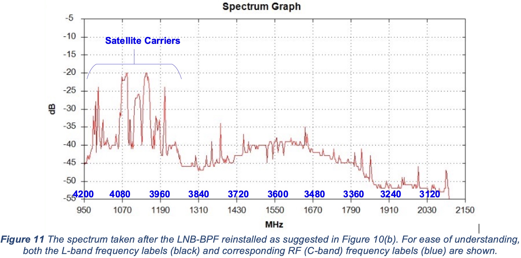
The spectrum plot collected after the BPF reinstallation is shown in Figure 11 below. After the adjustment, the 5G carriers were successfully filtered out as expected.
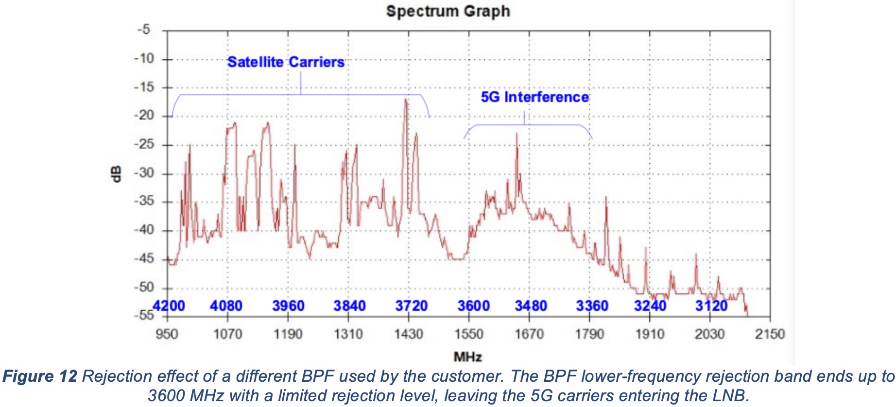
For comparison purpose, Figure 12 below also shows the LNB output spectrum using the old BPF. This legacy BPF from another vendor can only provide 5G interference rejection to a limited degree, effective up to 3.6 GHz. Consequently, the 5G carriers near 3.45 GHz remained visible even after use of the filter.
A critical limitation of this legacy filter is that when the mobile terminal operates in another country and encounters 5G carriers in 3.7 to 3.9 GHz range, the interference will fall into the filter’s passband. The unwanted 5G carriers can saturate the LNB, robbing the output power of the satellite carriers, rendering the entire C-band satellite link unusable by the terminal.
Therefore, it is a sound decision to replace the old filter with AsiaSat BPF-3925 that can reject a wider band of 5G interference, allowing the terminal to successfully lock on satellite carriers at the higher end of the C-band.
4. Diagnosis Guidelines for BPF Installation
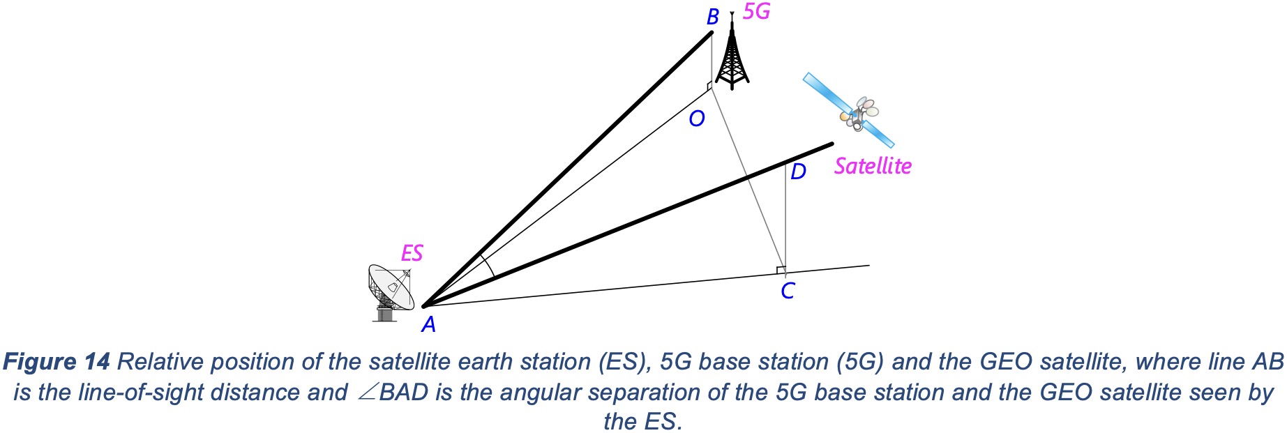
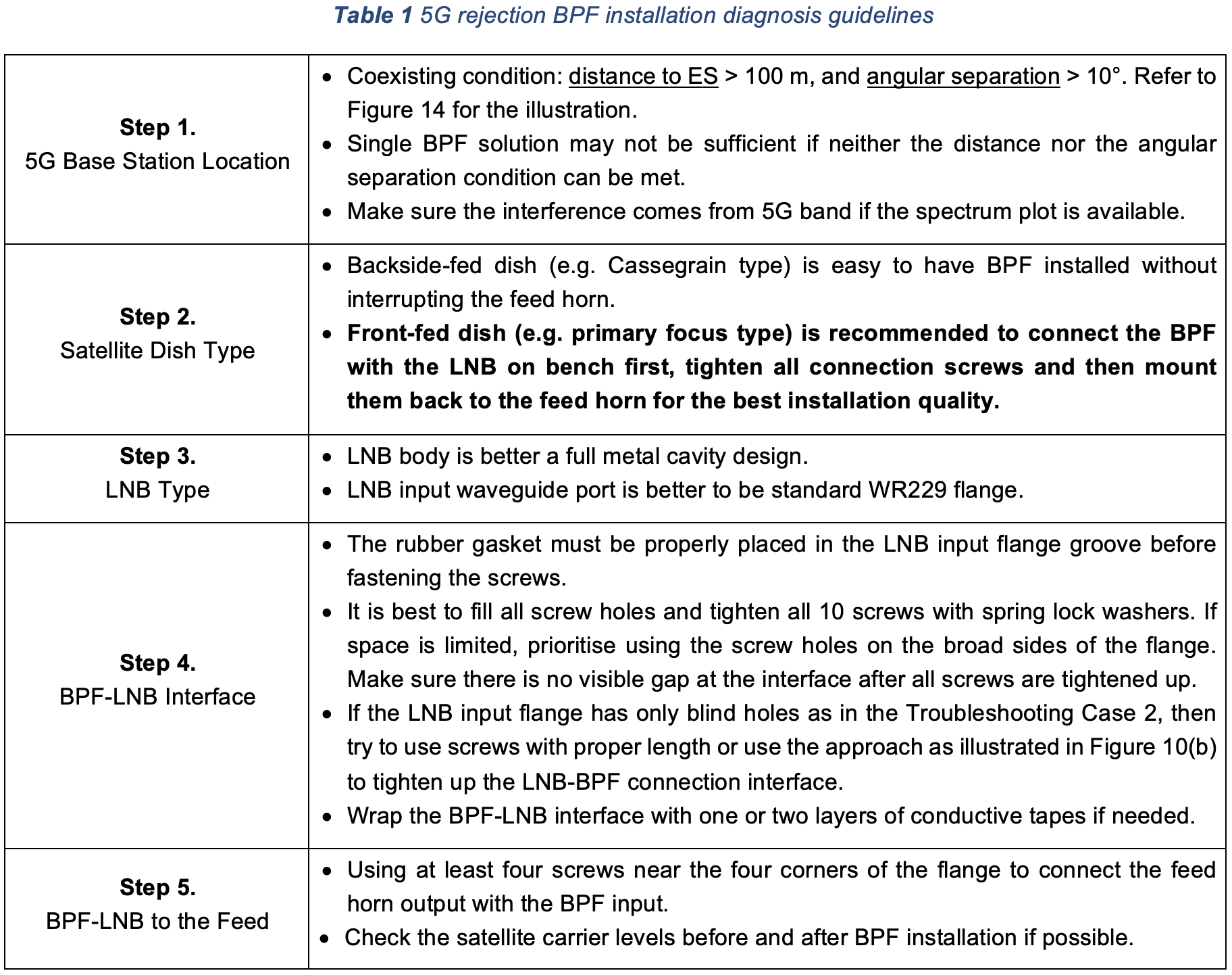
Based on our real-world experience troubleshooting the problems with 5G interference and BPF installation, we think it may be worthwhile to summarise our experience and to provide some diagnosis guidelines for our customers. Some of the factors that need to be considered are:
- the location of the nearest 5G base station
- satellite dish type
- LNB type
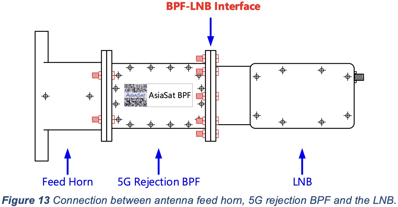
- the quality standard of the BPF installation (i.e. BPF-LNB interface) (see Figure 13)
The guidelines are set out in Table 1 below, with the most important tip being to make sure that the BPF-LNB interface is tightly connected. If the LNB used is similar to the one shown in Figure 2(a), it may be better to upgrade it with a model having standard waveguide flange and full-metallic body enclosure. For a step-by-step installation guide, please watch the video on our website.
4. Conclusion
In this White Paper, typical issues with BPF installation are diagnosed and eventually solved. The cause of the partially-rejected interference is the insufficiently tightened BPF-LNB waveguide flange interface where the 5G signal could be directly coupled in without passing through the BPF. The solution is to simply tighten up all the screws between the BPF and LNB before re-mounting them onto the antenna feed horn. This White Paper provides some general diagnosis guidelines to help with BPF installation and troubleshooting.